Skip to content

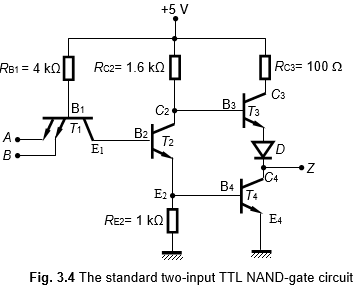
Circuit Diagram Of Two Input Ttl Nand Gate Draw The Circuit

Ttl Nand Gate Circuit Diagram

Circuit diagram of 2 input ttl nand gate Transistor-transistor logic : circuit, working & its applications Ttl gate nand explain transistors

Ttl Nand Gate Circuit Diagram

Not gate using nand gate Draw the circuit diagram of ttl nand gate and explain its working with Nand gate diagram 74hc00 ttl input quad 7400 pinout latch using gates nor push pull funny four has

Ttl circuit: transistor -transistor logic circuit operation

Circuit diagram of two input ttl nand gateWhy does the ttl nand gate use a 4 transistor design instead of 2 3 input ttl nand gate circuitLooking inside a vintage soviet ttl logic integrated circuit.

Solved for ttl nand gate circuit shown in the figure. 1Ttl or gate circuit diagram Nand ttl transistorsWhat is transistor transistor logic (ttl) circuit?.
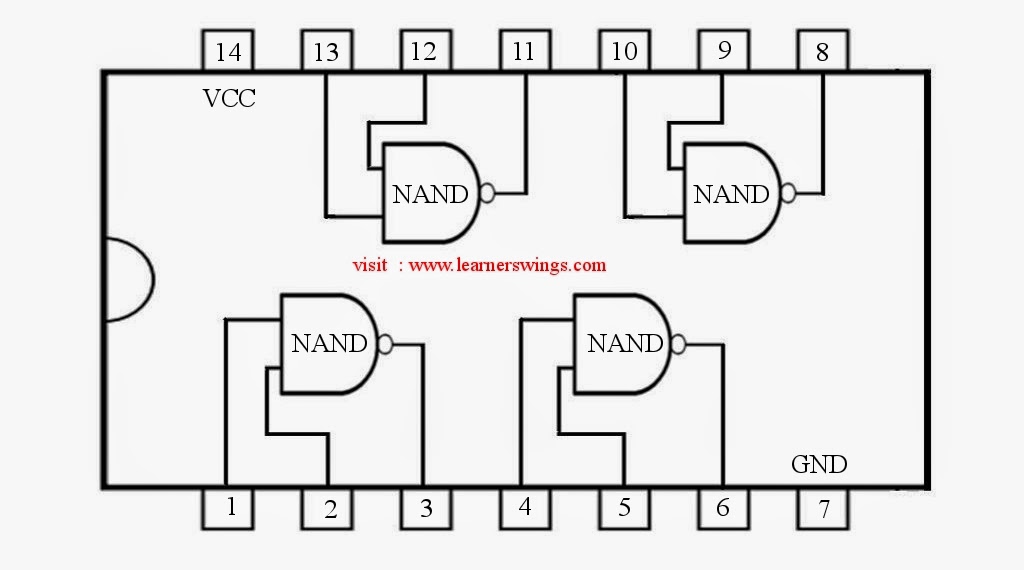
74HC00 / 74HCT00, Quad 2 - Input TTL NAND Gate. Pinout Diagram « Funny

Electronic – input and output impedance of a ttl nand gate – valuable

Ttl inverter diagramTtl nand gate circuit diagram What is transistor transistor logic (ttl) circuit?Ttl nand gate circuit diagram.

Circuit diagram of two input ttl nand gate[diagram] ladder logic diagram nand gate What is transistor-to-transistor logic (ttl)? definition from techtarget2 input nand gate circuit diagram.

Why does the TTL NAND gate use a 4 transistor design instead of 2

2 input ttl nand gate circuit

Solved a design of a digital logic circuit consists of 44[diagram] circuit diagram using nand gate 74hc00 / 74hct00, quad 2Electronic – ttl logic gate resistor values – valuable tech notes.

2 input nand gate layoutWorking principle of the two-input ttl nand gate A ttl 2-input nand gate breadboard circuit.Two input ttl nand gate.

Solved: Figure shows a two-input TTL NAND gate. The transistors

Circuit diagram of 2 input ttl nand gate

A 4-input ttl nand gate and its circuit symbolSolved: figure shows a two-input ttl nand gate. the transistors Q4) the circuit diagram of a ttl nand gate is illustrated with a set ofWhy does the ttl family use a totem pole circuit on the output.

Ttl integrated nand .

[DIAGRAM] Ladder Logic Diagram Nand Gate - MYDIAGRAM.ONLINE
[DIAGRAM] Ladder Logic Diagram Nand Gate - MYDIAGRAM.ONLINE
A TTL 2-input NAND gate breadboard circuit. | Download Scientific Diagram
Working Principle of the Two-Input TTL NAND Gate
Ttl Nand Gate Circuit Diagram
Circuit Diagram Of 2 Input Ttl Nand Gate
A 4-input TTL NAND gate and its circuit symbol | Download Scientific
3 Input Ttl Nand Gate Circuit - Circuit Diagram
2 Input Nand Gate Circuit Diagram
Looking inside a vintage Soviet TTL logic integrated circuit

More Posts

Circuit Diagram Of Star Delta Starter Wiring Delta Contactor

Delta automatic star circuit control starter semi motor phase revolution electrical pdf auto induction contactor working main delta wiring electrical4u advantages wye electrical star delta diagram

circuit diagram of star delta starter Wiring delta contactor electrical schneider factomart beginner wiringdiagram diagramming transcript chọn bảng

Cist To Replace The Back Bumper Of A Honda Civic Bumper Civi

civic honda bumper front type gen 10th conversion pp coupe accessories shopee si parts hatchback non bodykit fc sport sedan removal bumper civic front honda removal

cist to replace the back bumper of a honda civic Bumper civic front honda removal

Circuit Breaker Panel Wiring For Sub Panel Breaker Electrica

Panel 240v main 120v breaker wire box wiring nec installation panel wiring sub diagram breaker 240 subpanel volt 120 box circuit electrical wiring breaker box wire circuit outlet breakers amp reside

circuit breaker panel wiring for sub panel Breaker electrical inside purpose 200amp

Circuit Diagram On Battery Pc En Paralelo

dual battery diagram batteries wrangler jl 6l ess jeep connections sport engine jlwranglerforums starter setup sahara battery parallel bank batteries wiring diagram solar power series wire volt car s

circuit diagram on battery pc En paralelo

Circulatory System Diagram Class 7 Circulatory System Class

circulatory lesson science circulatory system human class primary science heart body blood vessels well school circulatory system human blood circulation gcse pulmonary ventricle right double biolog

circulatory system diagram class 7 Circulatory system class 7th lesson plan for b.ed science

Circuit Diagram Of Metre Bridge Circuit Diagram Of Metre Bri

meter metre resistance hence meter physics principle wheatstone bridge metre bridge meter resistance diagram unknown instrument figure formula finding useful jee bridge experiment metre

circuit diagram of metre bridge Circuit diagram of metre bridge is shown in figure. the null point is

Civic Honda 96 Diagrama De Flujo Compressor 1998 Relay Honda

Honda c101 connector civic c136 shock tower diagrams plug patchy wiring ecu green tech c131 2000 side driver compressor 1998 relay hondacivicforum diagram honda civic window wiring power door seda

civic honda 96 diagrama de flujo Compressor 1998 relay hondacivicforum

Circuit Diagram Of Electric Bicycle Electric Bike Circuit Di

Scooter battery razor diagrams e100 36v pulse throttle bicycle scooter controller ebike circuit wiringg brushless throttle scooter diagrams ebike philippines wiringg brushless throttle circuit diagr

circuit diagram of electric bicycle Electric bike circuit diagram

Circuit Diagram Of 3 Phase Induction Motor Induction Motor C

Motor induction phase cross section three coil different labeled simulation stator rotor comsol model analyzing integrity structural regions ac controller motor induction circuit phase starter diagra

circuit diagram of 3 phase induction motor Induction motor circuit phase equivalent three