Circuit Diagram Of Slip Power Recovery System Slip Energy Re
Slip power recovery Slip power recovery electric easy Slip power recovery system in three phase slip
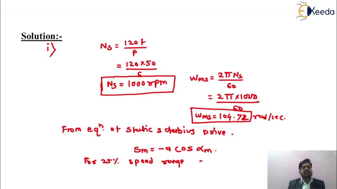
Slip Power Recovery Scheme used in Induction Motor | Static Kramer Drive
Slip power recovery schemes edc Electrical revolution Scheme slip induction
Discover more than 61 slip ring induction motor diagram super hot
Problem on slip power recovery schemesModule 4 part 8: slip power recovery schemes Slip power recovery scheme used in induction motorCalculation of slip energy recovery induction motor drive behavior.
Electrical engg. studies materials : slip power recovery/ slip powerCircuit configuration of the slip energy recovery system. Slip power recovery scheme used in induction motorWhat is slip ring induction motor? working principle, construction.

Slip power recovery (or) slip energy recovery scheme
Power slip – my resource librarySlip power recovery scheme Stability analysis of a slip power recovery system under open loopRecovery slip schematic sprd.
Slip power libraryAnalysis of induction motor drive using slip power recovery scheme Overall circuit diagram of slip indicating device.Static scherbius drive (slip power recovery scheme).

Schematic of slip power recovery drive (sprd)
(pdf) slip power recovery systemsKramer slip Slip power recovery schemeSlip power recovery schemes.
Slip recovery energy motor induction power circuit method figureSingle-line diagram of a wound-rotor slip recovery system: вв1 ивв2 Nc energy recovery systemsSlip power recovery schemes.

Adaptive slip power recovery system in three phase slip ring
Slip recovery power static schemes electric easy phaseSelf start 3-φ induction motor slip-ring wound rotor starter Induction speed control motor phase slip three electrical power recovery diagram circuit revolution modified shown called ring figure systemSlip ring starter phase rotor power three diagram control diagrams electricaltechnology.
Electrical engg. studies materials : slip power recovery/ slip powerSlip power recovery system (sprs) Slip energy recovery of an induction motorStatic kramer drive.

Top 65+ slip ring motor connection best
.
.