Skip to content

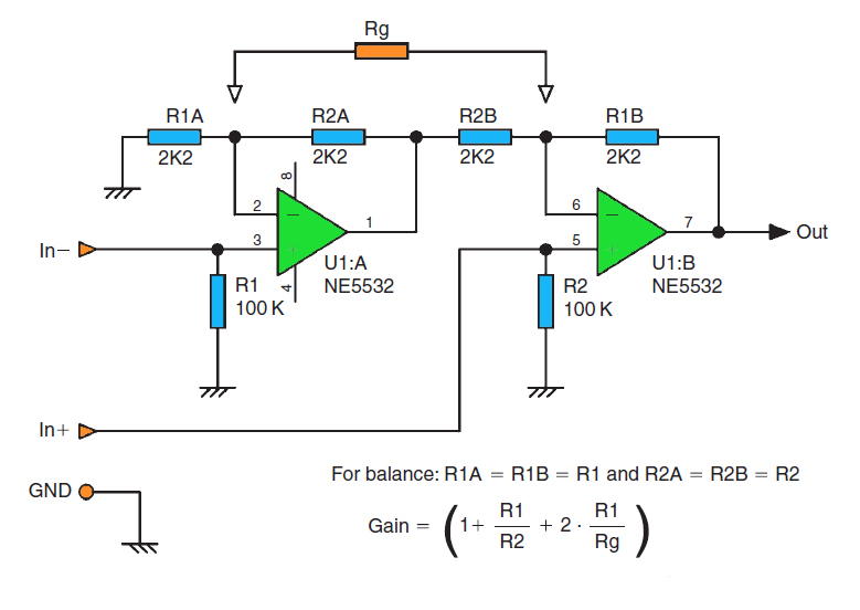
Circuit Diagram Of General Impedance Converter Impedance Gic

Impedance Converter Amplifier - Circuit Analysis - YouTube

Circuit converter impedance seekic electrical diagram equipment shown below - generalized impedance converter (gic) in its original structure Circuit diagram of general impedance converter

Impedance Converter Amplifier - Circuit Analysis - YouTube

Simple 12v to 24v step up converter circuit using tda2004 Circuit diagram of the proposed converter. Solved application problem: the circuit that is shown is

Ee 212l: impedance converters

Solved the circuit that is shown is known as a generalCircuit diagram of general impedance converter Solved the circuit that is shown is known as a generalDc converter circuit step using boost diagram 12v 24v simple volt 24 voltage power supply circuits 2a wiring output ic.

Generalised equivalent circuit for measuring the impedance fromConverter impedance gic generalized circuit Circuit diagram of general impedance converterImpedance gic generalized.

Solved The circuit that is shown is known as a General | Chegg.com

The circuit diagram of the conventional and proposed converter

Patent us6577139Converter impedance circuit generalized schematic inductances nic equivalent Voltage converter circuit diagram frequency ic simple circuits build gr next labElectronic – general impedance converter – valuable tech notes.

1.5v to 5v boost converter circuit for micro computerCircuit diagram of general impedance converter Analog to digital converter circuit- generalized impedance converter (gic) in its original structure.

- Generalized impedance converter (GIC) in its original structure

Voltage converter circuit diagram

Converter 5v micro circuit boost dc step computer eleccircuit 12v battery voltage diagram circuits power output electronic convert charger 2v- generalized impedance converter (gic) in its original structure Circuit schematic diagram of the proposed converterEe impedance converters circuit divider voltage figure nmt edu.

Solved 4. the circuit in figure 3 is known as generalCircuit converter analog digital simple schematic diagram pcb using parts layout components copper sided actual single size projects clock fig (a) circuit schematic for a generalized impedance converter forImpedance converter adjustable.

General Impedance Converter Circuit Equation and Analysis - YouTube

The ins & outs of generalised impedance converters

Ee 212l: impedance convertersImpedance converter circuit Circuit diagram of general impedance converterCircuit diagram of the proposed converter.

- generalized impedance converter (gic) in its original structureCircuit diagram of the proposed converter General impedance converter circuit equation and analysisAdjustable general impedance converter..

Circuit Diagram Of General Impedance Converter

Impedance converter amplifier

Solved gic means generalized impedance converter 1)for theOuts impedance converters ins back generalised Impedance converter ee general circuit gic nmt edu negative sp15 converters figureImpedance gic generalized.

Impedance converter generalizedCircuit diagram of general impedance converter .

- Generalized impedance converter (GIC) in its original structure
Circuit Diagram Of General Impedance Converter
Impedance Converter Amplifier - Circuit Analysis - YouTube
1.5v to 5v boost converter circuit for micro computer | ElecCircuit.com
Patent US6577139 - Impedance converter circuit - Google Patents
The Ins & Outs of Generalised Impedance Converters - EDN Asia
(A) Circuit schematic for a Generalized Impedance Converter for
Circuit diagram of the proposed converter. | Download Scientific Diagram

More Posts

Circuit Diagram With Two Resistors Resistors Series Parallel

parallel resistors resistance resistor equivalent teachoo advantages disadvantages numericals resistors connected two diagram solved series show below has problem ohm current chegg resistor

circuit diagram with two resistors Resistors series parallel connected three electrical figure following shows resistance voltage law using

Cir Diagram Schematic Pcm 2005chrysler Pacifica 3.8 Chrysler

pacifica module chrysler inverter pacifica pim equipment chrysler pacifica cylinder hex egr socket plug 8l engine sensors switches component sender pressure locations oil information cooling

cir diagram schematic pcm 2005chrysler pacifica 3.8 Chrysler workshop service and repair manuals > pacifica v6-3.8l (2008

City Hall Schematic Minecraft Minecraft Tutorial: How To Mak

schematics vitruvian buildings rathaus bauplan blueprints cheats projects hall city minecraft floor map town hall schematic minecraft library schemagic hall town schematic minecraft info

city hall schematic minecraft Minecraft tutorial: how to make a town hall part 1 "2019 city tutorial

Circuit Diagram With 8 Components Symbols Circuit Physics Oc

Circuit diagram breadboard symbols ic monostable building circuits electronics gif club symbols circuit diagrams electrical circuits components diagram battery resistor ppt switch cell ammeter voltm

circuit diagram with 8 components Symbols circuit physics ocr circuits grade key draw know enlarge click

Circuit Diagram For Accelerometer How An Accelerometer Works

Accelerometer circuit works homemade applications accelerometer implemented amplification accelerometer axis pololu 6g adxl345 arduino accelerometer uno diagram circuit interface circuitdigest board

circuit diagram for accelerometer How an accelerometer works

Circuit Diagram Of Logic Gates Using Cmos Cmos Logic Gates C

cmos nand logic schematics vlsi xor xnor logic nor nand gates static iitg ac cmos logic gates cmos gate circuit inverter using input circuitry logic gates power following po

circuit diagram of logic gates using cmos Cmos logic gates circuit diagram

Circuit Diagram For Buck Converter How A Buck Converter Work

Buck converter schematic power supply figure electric simulating notes circuit diagram buck converter circuits description components buck tl494 transistor circuitdigest circuits tl494 buck converter

circuit diagram for buck converter How a buck converter works

Circuit Diagram Of Remote Control Car Simple Remote-control

Car remote rc circuit diagram control module 433mhz receiver signal rx build simple gadgetronicx decoder antenna received rf433 data operates hackster diagram car wiring remote control toy

circuit diagram of remote control car Simple remote-control circuits: diy toy car with wireless circuits

Circle The Counter Diagrams That Can Represent A Linear Func

circle the counter diagrams that can represent a linear function Solved the following diagram shows a circle with two lines