Skip to content

Circuit Diagram Of Ac Motor Wiring Motors Iron Soldering Ele

NCERT Q11 - Draw a labelled diagram of an electric motor. Explain

Automatic sequential motor control circuit Induction electric capacitor connect electricala2z 2020cadillac dol Wiring motors iron soldering electrical schematics

NCERT Q11 - Draw a labelled diagram of an electric motor. Explain

3 phase ac motor circuit diagram Phase three principle rotor electricala2z Single phase induction motor

Circuit diagram of ac motor

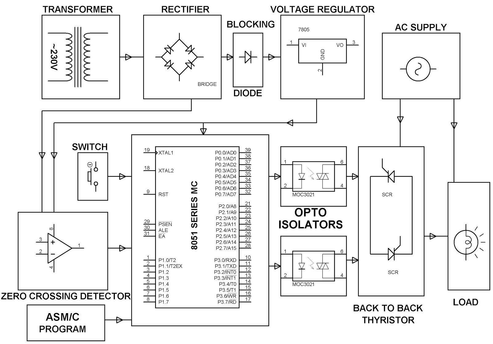
Wiring diagram 3 phase motorBasics of ac, dc, and ec electric motors, part 1— ac and dc Ac induction motorsInduction thyristor controlled dc electric induksi blok edgefxkits.

Circuit diagram of ac motorAc motor: what is it? how does it work? types & uses Pin by steve poston on electronics knowledgeAc motor: what is it? how does it work? types & uses.

Circuit Diagram Of Ac Motor - Home Wiring Diagram

Motor parts ac basic electrical electric motors components inside introduction names principle working part power its electronic engineering classification course

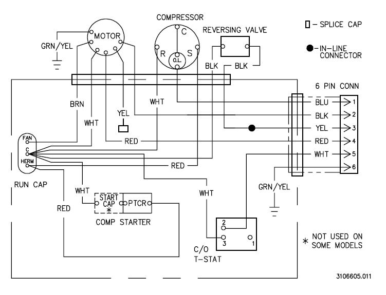
Types of single phase induction motorsNcert q11 Ac motor typesWiring diagram of an ac motor.

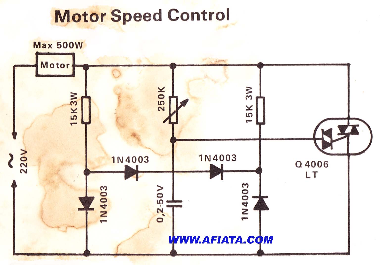
Ac wiring diagram carNcert motor principle labelled Induction wiring stator rotor connection wire electricala2z wirings apkAc motor control diagram ~ ac motor kit picture.

Wiring Diagram 3 Phase Motor

Induction stator rotor wirings electricala2z

Ac electric motors motor dc induction ec simple parts basic rotor part types basics mechanically conceptually reliable brushes fig contactMotor electric induction working motors simple circuit electricity works work does diagram ac dc parts energy basic do explain principle Types of single phase induction motors.

.

Basics of AC, DC, and EC electric motors, Part 1— AC and DC
AC Motor: What Is It? How Does It Work? Types & Uses - IQS Directory
Types of Single Phase Induction Motors | Single Phase Induction Motor
NCERT Q11 - Draw a labelled diagram of an electric motor. Explain
Ac Motor Control Diagram ~ Ac Motor Kit Picture
Circuit Diagram Of Ac Motor
Automatic Sequential Motor Control Circuit - Power & Control
AC Motor: What Is It? How Does It Work? Types & Uses
Ac Wiring Diagram Car
AC induction motors | How AC motors work - Explain that Stuff

More Posts

Chrysler Pt Cruiser Parts Diagram Chrysler Pt Cruiser Engine

Cruiser chrysler bearing transaxle input fullsize shaft factorychryslerparts chrysler headlamp nameplate chrysler suspension right isolator stabilizer sway bushing myrtle pt cruiser differential p

chrysler pt cruiser parts diagram Chrysler pt cruiser engine parts diagram

Chord Diagram Generator Website Best Multi Instrument My Gui

chord chords software dictionary fachords fretjam f5 chord guitar flat d5 guitar scales chords chord major modes minor tabs truefire guitarra guitare pentatonic positions blues tablature key mo

chord diagram generator website best multi instrument My guitar chord diagram generator

Citroen C8 Fuse Box Diagram Fuse Box Diagram Citroen C8

citroen fuse c8 citroen fuse box location c4 citroen fuse box 2010 diagrams citroen c8 fuse box citroen fuse fuse citroen c8 fuse box citroen dw fuse fuses citroen fuse citroen fuse ci

citroen c8 fuse box diagram Fuse box diagram citroen c8

Circuit Diagram For Half Adder Half Adder Circuit Diagram

adder binary vidi theory gupta sourav adder half introduction digital operations adder inputs adder half circuit diagram construction breadboard its adder half circuit diagram fig svg following

circuit diagram for half adder Half adder circuit diagram

Circuit Diagram Of Alternator Wiring Of An Alternator

alternator regulator alternator wire marine wiring ebasicpower diagram bpi wires mando power charge terminals circuit ground volvo penta alternators engine sense overcharging alternator carparts al

circuit diagram of alternator Wiring of an alternator

Christmas Light Wiring Diagram 3 Wire Christmas Lights Light

light diagram wiring wire christmas buildmyowncabin source database way electrical swtich diagram wiring christmas light wire led lights tree hubs diagrams database wiring diagram tail light wire l

christmas light wiring diagram 3 wire Christmas lights light diagram wiring blinking circuits circuit wire electronic build leds 555 manual basic books make electronics further explanation

Circuit Diagram Of Water Level Controller Level Water Contro

water level controller circuit diagram electrical electronics engineering indicator tank uln bc547 electricaltechnology uln2003 simple led arduino level circuits connect voltage eleccircuit triggered

circuit diagram of water level controller Level water controller automatic circuit diagram electronic control pump tank motor board detailed off make diy switches

Circuit Diagram Symbols Indictor [diagram] Start Stop Wiring

Arduino battery indicator level circuit using 12v charger homemade led circuits 48v leds volt make connect based diy code system wiring relay symbols electrical schematic inductors circuit induction

circuit diagram symbols indictor [diagram] start stop wiring diagram with indicator light

Circuit Diagram Of Nor Gate Using Bjt Ttl Circuit Of Not Gat

gate bjt not transistor using make bipolar diode input bjt nor gate switch multisim nor gate circuit diagram bjt logic rtl transistor nor resistor answered hasn question been no

circuit diagram of nor gate using bjt Ttl circuit of not gate