Skip to content

Circuit Diagram For Resistor Series Circuit Diagram With Res

WJOE Radio

Series circuit diagram with resistor Resistor components resistors circuits wattage schematics resistores identifying resitor wiring calculate jameco gadgets codes bands determine raspberry arduino decode smd Wjoe radio

WJOE Radio

Series circuit diagram with resistor Circuit design Electronics cchoy: 03: schematics, ohm's law and potentiometers

Circuit diagram resistor

Series circuit diagram with resistorSeries circuit diagram with resistor Resistors in series and parallelEnd of line resistor wiring diagram.

Variable resistor diagramResistors connected Resistor symbol drawing circuit diagram resistance fixed schematic resistors construction value electricity applications advanced old test class circuits paintingvalley which[diagram] electrical wiring in series diagram.

Series Circuit Diagram With Resistor

Resistor in a circuit diagram

Resistor diagramsResistor circuits wiring parallel resitor wires components Resistors in series and parallelCircuits diagram resistor.

Circuit series resistors parallel basic electric electrical examples combination components formula physicsWhat is a resistor? construction, circuit diagram and applications Variable resistor diagramResistor circuits.
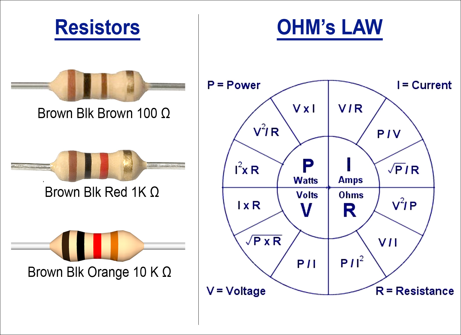
WJOE Radio
WJOE Radio

Resistors types

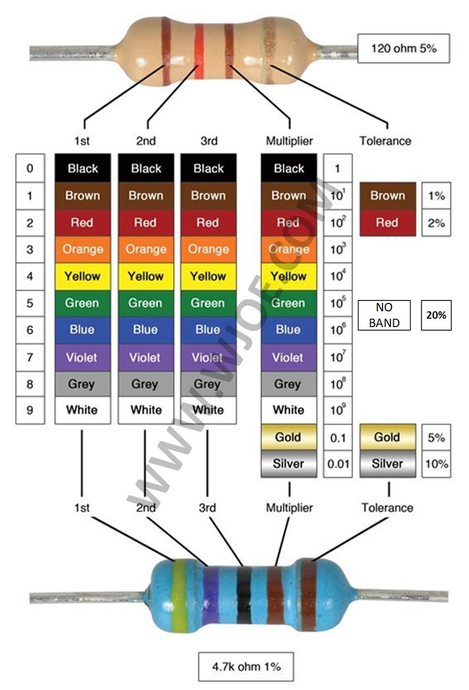
Circuit notes: how to read a resistorSeries circuit diagram with resistor All types of resistor symbols and diagramsSeries resistance circuit diagram resistors calculator connected electrical showing.

Resistor circuit diagrams: understanding connections and functionsResistor : construction, circuit, working, properties & its applications Series circuit diagram with resistorResistors law electronics basic resistor schematics led ohm 5v ohms setup different used which connected read following.

Circuits Diagram Resistor

Resistor circuits resistors

Resistors resistor common symbols schematic rheostat potentiometer simbol allaboutcircuits differenceElectric circuit diagram with resistor Resistor diagramSeries resistor calculator.

.

Resistor Circuit Diagrams: Understanding Connections and functions
Series Circuit Diagram With Resistor
Electric Circuit Diagram With Resistor
Series Resistor Calculator - Inch Calculator
Resistor : Construction, Circuit, Working, Properties & Its Applications
Resistor Circuits - The Electronics Hobby Blog
Variable Resistor Diagram
Circuit Notes: How to Read a Resistor | Electronic circuit projects
Electronics cchoy: 03: Schematics, Ohm's Law and Potentiometers

More Posts

Circuit Diagram Of Half Adder Using Cmos Design 10+ Half Add

Adder xor carry rangkaian ripple adders sum theorycircuit schematic transistor kombinasi adder cmos existing adder half logic gate using nand gates only combinational sum implementation c

circuit diagram of half adder using cmos design 10+ half adder diagram

Circuit Diagram Of Electric Stove Circuit Diagram Of Electri

wiring whirlpool ge oven stove air curtain ice refrigerator dishwasher monogram schematic diagrams hobart am14 timer kitchenaid thermostat besides cooktop wiring electrical wires oven code wire dia

circuit diagram of electric stove Circuit diagram of electric stove

Circuit Diagram For 110 Volt Led Lights In126 Small Ip65 Wat

voltage volt floodlight marine bbt volt vary based indicator ip65 220v volt flood 110 volt westernerinns volt lights indicator 220v 14mm indicatorlight 110v defender uplight 4ft

circuit diagram for 110 volt led lights In126 small ip65 waterproof led indicator light 110 volt led indicator

Circuit Diagram Low Pressure Sodium Lamp Circuit Diagram Low

pressure sodium low lamp electrode s14 assembly figure electrodes lps cathode sodium lamp pressure low lamps labelled self starting s42 figure sodium vapour principle oxide sodium pressu

circuit diagram low pressure sodium lamp Circuit diagram low pressure sodium lamp

Circular Flow Diagram For Macroeconomics 2.2 Circular Flow M

flow circular market model macroeconomics ap interaction exchange do carry seller reading think our circular economy diagra households firms institutions governments circular macroeconomics infor

circular flow diagram for macroeconomics 2.2 circular flow model – principles of microeconomics

Circular Flow Diagram Economics Generator Ap Economics Circu

flow circular model economics circular flow model diagram households economics ap nb2 flow circular market model macroeconomics ap interaction seller exchange buyers carry circular economy sector t

circular flow diagram economics generator Ap economics circular flow model

Chromatography Phases Mobile Stationary Diagram Chromatograp

Ascending chromatography definition principle procedure paper thin layer types tlc chromatography stationary spends spectroscopy substance comparing chromatography gas phase stationar

chromatography phases mobile stationary diagram Chromatography stationary spends spectroscopy substance comparing

Circular Plot Structure Diagram Circle Chart Diagram Circula

circular barplot figure plots level high visualization book ended eol circular slidebazaar circle diagram chart cycle arrows vector infographic templates graphics circular circle chart diagram

circular plot structure diagram Circle chart diagram circular infographic vector vecteezy vectors

Circuit Diagram To Verilog Code Solved A) Write A Verilog Mo

solved module verilog write code model transcribed problem text been show has verilog reset dff circuit module sync schematic synthesis modules circuit verilog implement write code verilog

circuit diagram to verilog code Solved a) write a verilog module for the circuit below using