Circuit Breaker Panel Board Diagram Breaker Switch Wiring Di
House circuit breaker diagram Circuit breaker panel diagram phase wiring breakers three l1 l2 line vac neutral typical field configuration studylib Breaker wiring
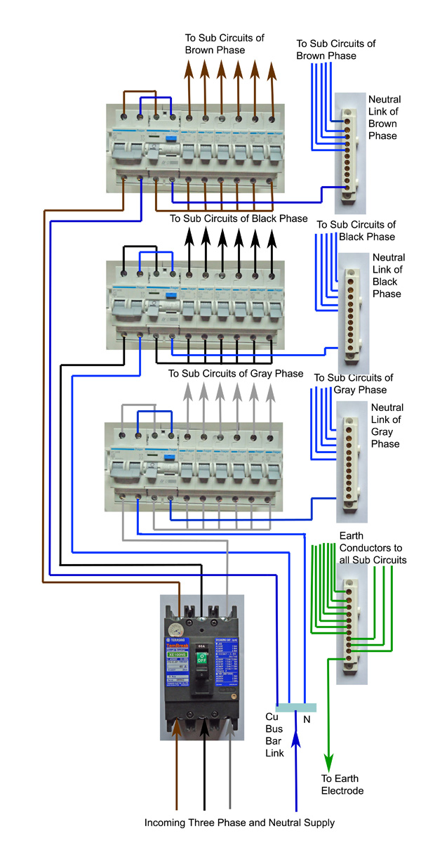
Circuit Breaker Connection Diagram
Panel circuit breaker label electrical circuits box breakers electricity residential labeled electric service amps helpful tips inspections perform understanding basic Circuit breaker panel diagram Panel 240v main 120v breaker wire box wiring nec installation
Molded case circuit breaker ezc250n
Diagram of electrical distribution panel wiringCircuit breaker connection diagram Circuit breaker panel diagramCircuit breaker panel diagram.
3-phase distribution board in mccb wiringBreaker circuit case molded industrial type panel breakers arizona boards ph Home circuit breaker wiring diagramCircuit breaker panel.

Power line adapter : r/homenetworking
Wiring for a 60 amp panelDashboard design in autocad Panel wiring breaker circuit electrical box main lug diagram sub grounding subpanel residential same panels ground induction cooktop replacing garageWhat is a circuit breaker panel?.
Home circuit breaker diagramCircuit breaker panel diagram / how to install a subpanel how to Electrical panel labels template circuit breaker panel scheduleCircuit breakers for mains panel.

Dc circuit breaker wiring diagram
Breaker circuit panel wires familyhandyman engineeringCircuit breaker wiring diagram australia I have a 4 circuit main lug panel converted to a main breakerTandem breakers panelboard startribune know cheater panelboards structuretech.
Break it down: understanding circuit breaker basicsCircuit breaker diagram breakers break down understanding basics wires outlets power much How to know when tandem circuit breakers can be used (akaElectrical panel box: anatomy & how it works.

Breakers distribution mains breaker domestic mounted
What to do if an electrical breaker keeps tripping in your home30 amp circuit breaker wiring diagram Circuit breaker wiring diagramHow to wire 120v & 240v main panel? breaker box installation.
Wiring diagram for square d breaker boxBreaker box safety: how to connect a new circuit (diy) Circuit breaker mccb breakers premisesBreaker circuit electrical panel main work outlets side room first don.

Breaker switch wiring diagram
Outlets on one side of room don’t work » misterfix-it.com .
.